Saturday, October 29, 2011

Non-Lab Entry: Official Arduino Website

Summary: A great website for projects and project ideas


Screenshot: 


Site link: 
http://www.arduino.cc/playground/Projects/Ideas

Review:
Not only does this website provide a range of great projects for arduino, but it also provides information on circuits, schematics, arduino parts, arduino products and even tutorials. This website is really good for learning about specific arduino parts such as shift registers or transistors. Through the main site, you may also download the arduino IDE for free as well as buy arduino starter kits and specific parts.

This is very useful for learning more about arduino. We can also order parts from here and start to build bigger projects in school such as wall-avoiding robots or drink-serving robots. There are tutorials to follow and things to do on this website.

Non-Lab Entry: Sparkfun

Summary: This website is great for buying and learning about arduino parts and products

Screenshot:


Site link: http://www.sparkfun.com/

Review:
Sparkfun provides a lot of equipment for arduino including kits and advanced items as well. Its main focus is products but this website has tutorials as well. Like with the products, there are beginner tutorials as well as much more advanced tutorials.

Also, it is very easy to navigate and very user friendly. There are product reviews as well as product suggestions and recommendations. Another great thing is that there are product details which explain what each and every part does. There are so many available products that one could spend an entire day just viewing and reading details about them.


Non-Lab Entry: Simon Game

Summary: This website explains how to make a Simon Says game using arduino.

Screenshot:

Site Link: http://www.codeproject.com/KB/system/arduino_simon.aspx

Review:  This specific entry talks about how to make a Simon Says game using arduino. It gives you the code to do it and explains what each part of the code does, its very useful and easy to use, especially for beginners.

 It also provides a schematic of the arduino as well as the program files so if you have the necessary materials, you can make the Simon game and upload the code to make it work right away. It is also very simple and could teach a few things about  programming. I would like to make a simon says game because it doesn't seem too complicated.

Non-Lab Entry: Hack N Mod

Summary: Hacknmod is a great website for lots of really cool, advanced arduino projects.

Site Screenshot:


Site link: http://hacknmod.com/hack/top-40-arduino-projects-of-the-web/


Review:
This website has a lot of projects based on arduino. The specific link provided above talks about 40 really cool projects that this site has to offer. The projects vary from making a wall-avoiding robot, to a gameboy to a UAV spy plane.

However, the projects are quite advanced and should only be attempted after we gain a better understanding of arduino's capabilities. I find the projects on this website to be really amazing, I have watched a few videos on the final results of these projects and most of them turn out really well.


Sunday, October 23, 2011

Circuit 11 - Larger Loads

Purpose:  To use a relay to switch currents between two LEDs

Equipment: 
  • Arduino x 1
  • Breadboard x 1
  • Arduino Holder x 1
  • CIRC-11 Breadboard Sheet x 1
  • Diode (1N4001) x 1
  • Transistor (P2N2222AG) x 1
  • Relay (SPDT) x 1
  • 10k Ohm Resistor x 1
  • 330 Ohm resistor x 2
  • LED x 2
  • Wire x  13

References:
Program Details:
This circuit is much more complicated than what we've used in the previous exercises. In this circuit a relay is introduced. A relay has a mechanical switch inside it which, when energized, trips and switches the current. In this circuit, we will use the switch to consecutively turn two LEDs on and off.

There is a diode in this circuit which is not really necessary but it is helpful. The purpose of it is to prevent energy loss as it makes sure that the electricity is flowing in one direction only. A transistor is used to switch the current into the relay. Without the transistor, we cannot control the Relay as it is connected to Pin2.

The programming in this is very simple, it is nearly the same as the very first program. There should be no difficulties in the programming part of this exercise. 


Time to Complete: 15 mins to assemble
                                 5 mins to code

Results: The first time we uploaded the program, nothing happened. This was because the transistor wasn't placed properly, so we flipped it around but only one light came on and it wasn't even blinking. We tried various things like switching LEDs, wires, resistors and even trying another group's Relay. We decided to rebuild it except this time we forget to add the diode. However when we ran it this time, the circuit worked. When we put the diode though, it stopped working. This was because we placed the diode in the wrong way so it didn't let any of the current pass through.

Picture:


Video: 


Tips: 
  • Place the transistor correctly, the flat side should be facing the relay and make sure it is not a temperature sensor.
  • Place the diode correctly, if it doesn't work then remove it from the circuit, it is not necessary
  • There are a lot of wires to connect, make sure you connect all of them

Further Work: I will change the delay time at a decreasing rate to make the LEDs blink faster and faster and then increase the delay to make them blink slower and slower. This will be similar to whats shown in the video. 

Program Modifications: The program is very similar to the one in the link below. The only change is the delay time which was switched from 1000 milliseconds to 500 milliseconds.

Program:

int ledPin =  2;                         // Relay is connected to pin2

void setup()  
{                
  pinMode(ledPin, OUTPUT); // ledPin is set as an output     
}

void loop()                     
{
  digitalWrite(ledPin, HIGH);    // The Led turns on
  delay(500);                           // Wait for 500 milliseconds
  digitalWrite(ledPin, LOW);   // The Led turns off
  delay(1000);                        // Wait for 500 milliseconds
}  

Circuit-10 - Temperature

Purpose: To get the arduino to display the room temperature

Equipment:

  • Arduino x 1
  • Breadboard x 1
  • Arduino Holder x 1
  • CIRC-10 Breadboard Sheet x 1
  • TMP36 Temperature Sensor x 1
  • Wire x 5

References:
Program Details:
Once again, a new piece of hardware is introduced in this circuit. It is the temperature sensor, and it looks exactly like the transistor. To tell them apart you must read the label on the head. If it says TMP36, then its a temperature sensor, otherwise, its a transistor. The temperature sensor requires 3 connections. One is connected to power (in this case 5v), one connected to ground and one connected to an analog pin for input. What the temperature sensor does is sense the temperature in the room and convert it into electricity and then sends it to the computer through the analog pin. Then using the program, we convert the electricity into numbers and use the program to display it.

Many new things are introduced in terms of programming. First up, a pre-made class named Serial. The purpose of Serial is to create a connection between the computer and arduino. It is also used to display the temperature inputted by the arduino through the line Serial.println();. Serial.begin(); is used to determine the speed at which the information is begin transferred back and forth. The other new concept introduced in this program is a method which has a data type. The method float getVoltage(int pin);, returns a value at the end of the method of type float. Float is a number with decimals between -3.40 and 3.40. The returned value is then used by the line of code that called the method, so now float temperature is equal to the value returned by the method.
    
Time to Complete: 5 mins to assemble
                                10 mins to code

Results: The circuit and the program both ran perfectly the first time. However, what the temperature sensor was displaying was wrong or out of range at first. After 30 seconds or so, it started becoming close to room temperature (around 18 - 25 degrees Celsius).

Pictures: 


Tips: 
  • Make sure you are using TMP36 temperature sensor and not the Transistor, they both look the same
  • If the temperature sensor is displaying temperatures above 35 degrees Celsius, then disconnect the wire from the computer, it may be over-heating.
  • Don't forget to click on Serial Monitor in the arduino program menu after uploading the program to display the values.  


Further Work: I will convert the temperature from Celsius to Fahrenheit by using simple math. I will also test what happens when I change the serial speed and what the optimal serial speed for the arduino is.

Program Modifications: The program is very similar to the one in the link below. However we did change one thing. We changed the delay speed to make the program display the temperature faster. Rather than displaying it every second, we made it display the temperature every half second or every quarter second.

Program:
 int temperaturePin = 0;    // The temperature senosor is connected to Analog Pin 0

void setup()
{
  Serial.begin(9600);        // A serial connection between the arduino and computer is made
}
 
void loop()                    
{
 float temperature = getVoltage(temperaturePin);  // Stores the voltage from temperaturePin into variable temperature 
 temperature = (temperature - .5) * 100;              // Converts from 10 mv per degree to degrees Celsius
 Serial.println(temperature);                                  // Prints the results in the serial monitor
 delay(500);                                                         // Delays 500 milliseconds
}

float getVoltage(int pin)                            // Returns the voltage from the analog pin 
{
 return (analogRead(pin) * .004882814); // Converting from a 0 to 1024 digital range
}

Thursday, October 20, 2011

Circuit-09 - Light Resistors

Purpose: To test how photo resistors responds to different amounts of light.

Equipment:
  • Arduino x 1
  • Breadboard x 1
  • Arduino Holder x 1
  • CIRC-09 Breadboard Sheet x 1
  • Photo Resistor x 1
  • 330 Ohm Resistor x 1
  • 10k Ohm Resistor x 1
  • LED x 1
  • Wire x 6

References:

Program Details: In this exercise, a Photo resistor is introduced. A photo resistor senses light and returns a voltage value. A photo resistor must be connected to a resistor, an analog pin, as well as to ground but it only has 2 pins. So how can this be done? Well the resistor and the analog pin are both connected to one lead and the ground is connected to the other lead.

Yet again, the programming is very simple. Only two new method are introduced, both which are very easy to understand. First map(lightLevel, 0, 900, 0, 255); what it does is assign a new range to lightLevel. Instead of it going from 0 - 900, it now goes from 0 - 255. Next is constrain(lightLevel, 0, 255); which makes sure that the range of lightLevel is between 0 - 255. The rest of the code is very simple as is the exercise. 

Time to Complete: 10 mins to assemble
                                10 mins to code

Results: The LED turned on and the circuit worked. However, when there is a change in the lighting in the room, the LED only grows dimmer or brighter very slightly. Even when the light was turned off, the LED grew slightly brighter. I think this is because the photo resistor is not the greatest so there was nothing wrong with the circuit or the program.

Photos: 

Circuit 9  with light on
Circuit 9 with light off
Tips:
  • Try controlling 2 or more LEDs rather than just one because this circuit is easy
  • Don't forget to attach a resistor connected to your photo resistor as shown in the schematic 


Further Work:
I will control the LED to do the opposite, so when there is a greater amount of light, the LED will grow brighter and when there is a lower amount of light, the LED will grow dimmer. I will also try to control a small servo using the photo resistor.

Program Modifications: The program is the exact same one from the link below
http://ardx.org/src/circ/CIRC09-code.txt

Program:
int lightPin = 0;   // photoresistor pin is connected to analog pin 0 
int ledPin = 9;    // LED pin is connected to pin 9

void setup()
{
  pinMode(ledPin, OUTPUT);    //sets the led pin as an output
}

void loop()
{
 int lightLevel = analogRead(lightPin);             // The light level from the lightPin is stored in lightLevel
 lightLevel = map(lightLevel, 0, 900, 0, 255); // Changes the range (from 0-900) to 0 - 255 (which is colour) 
 lightLevel = constrain(lightLevel, 0, 255);      // Makes sure that the value is between from 0 - 255
 analogWrite(ledPin, lightLevel);                    // Writes the value into ledPin from lightLevel 
 }// ends loop

Wednesday, October 19, 2011

Circuit-08 - Potentiometers

Purpose: To change the LED frequency by turning the potentiometer accordingly

Equipment:
  • Arduino x 1
  • Breadboard x 1
  • Arduino Holder x 1
  • CIRC- 08 Breadboard Sheet x 1
  • Potentiometer (10k Ohm) x 1
  • 330 Ohm Resistor x 1
  • LED x 1
  • Wire x 6

References:
Program Details:
In this circuit, we will be twisting a potentiometer to make an LED blink at different time intervals. The only new hardware introduced in this circuit is the potentiometer. What a potentiometer does is it reads some value between 0 and the amount of volts it is connected to, (in this case 5), and generates a value between those volts depending on the angle that the potentiometer is at.

In the program, we will be using the value generated by the potentiometer to cause a delay in the blinking time of the LED. This is done by the line sensorValue = analogRead(sensorPin). The analogRead method reads the position at which the potentiometer is at and then stores it into sensorValue. As we turn the potentiometer farther and farther away from 0 degrees, the delay between the LED going on and off  will increase. And as we turn the potentiometer closer to 0 degrees, the delay between the LED going on and off will decrease. This is shown by the last four lines of code in the program.

Both the program and the circuit are quite easy to understand and create.    


Time to Complete: 5 mins to assemble 
                                10 mins to program

Results: The circuit and program both ran perfectly the first time. As we twisted the potentiometer, the frequency at which the LED was blinking either increased or decreased depending on the way and angle we turn the potentiometer to.

Picture:


Video:


Tips:

  • Since this circuit is easy, use the schematic to create the circuit rather than using the breadboard. Later, double check if you did it right. This will help you understand schematics.

Further Work: I will try to control multiple LEDs by using only one potentiometer. If that is successful, then I will try to control a servo using the potentiometer. 

Program Modifications: This program is the exact same as in the link below.


Program:

int sensorPin = 0;       // sets input pin for the potentiometer
int ledPin = 13;          // sets input pin for the LED to pin13
int sensorValue = 0;  // stores values from the potentiometer

void setup()
{
  pinMode(ledPin, OUTPUT);  // intializes ledPin as an output
}

void loop() 
{
  sensorValue = analogRead(sensorPin);  // Values of sensorPin is read and stored into sensorValue 
  digitalWrite(ledPin, HIGH);                   // Turns on LED
  delay(sensorValue);                              // Delays LED for sensorValue milliseconds       
  digitalWrite(ledPin, LOW);                   // Turns off LED
  delay(sensorValue);                              // Delays LED for sensorValue milliseconds
}// end loop

Tuesday, October 18, 2011

Circuit-07 - Push Buttons

Purpose: To use a push button to complete a circuit.

Equipment:
  • Arduino x 1
  • Breadboard x 1
  • Arduino Holder x 1
  • CIRC-07 Breadboard Sheet x 1
  • Pushbutton x 2
  • 330 Ohm resistor x 1
  • 10k Ohm resistor x 2
  • LED x 1
  • Wire x 7

References: 
Program Details: 
Both the assembly of the circuit and the programming of the circuit are very simple in this exercise. In this circuit, we are basically controlling the LED staying on with the push button. When the push button is held down, the LED stays on, and when it is not pressed down, the LED stays off. This circuit should be easily built by following the schematic or the breadboard.

There is one new method introduced in this exercise, digitalRead().  What this method does is it reads the state of variable in the parameters and gives the output to another variable. In this example, buttonState = digitalRead(buttonPin); what this does is it reads the state (either HIGH or LOW) of buttonPin and assigns that read state as a value to the variable buttonState. Now in the program, according to the value of buttonState, the LED is either turned on or off.  

Time to complete: 5 mins to assemble
                               10 mins to program

Results: The first time we ran it, our push button did nothing. This was because we hadn't connected it to Pin2. The first button worked after that, but the second button still didn't do anything but this was because there was nothing about the second button in the program. The second button is used to turn off the LED in the second part of this circuit (if you decide to do it). 

Photo: 


Tips:
  • If the push button doesn't work, try flipping it around in 90 degree intervals
  • If the push button still doesn't work, try switching it with another one, the first one may have been nonfunctional
  • Don't forget to connect your resistors and wires 

Further Work: I will write the program to make the other button turn off the LED as well as make the LED's fade when they turn off and on.

Program Modifications:
The program is the same as the program in the link below:

Program:

// constants remain the same throughout the program
const int buttonPin = 2;      // pushbutton pin number
const int ledPin =  13;        // LED pin number

int buttonState = 0;           // buttonState 0 means it is currently doing nothing

void setup() 
{
  pinMode(ledPin, OUTPUT);     // initializes ledPin as an output   
  pinMode(buttonPin, INPUT);    // intializes buttonPin as an output    
}

void loop()
{
  buttonState = digitalRead(buttonPin);  // reads the state (HIGH or LOW) of buttonPin
  if (buttonState == HIGH)                   // if state is HIGH (meaning button is pressed) ...
  {     
    digitalWrite(ledPin, HIGH);             // turn on LED
  } 
  else                                                 // otherwise (meaning button is not pressed) ...
  {
    digitalWrite(ledPin, LOW);           // turn off LED
  }
}// end of loop


Sunday, October 16, 2011

Circuit-06 - Piezo Elements

Purpose: To play a short song using the Piezo Element

Equipment: 
  • Arduino x 1
  • Breadboard x 1
  • Arduino Holder x 1
  • CIRC-06 Breadboard Sheet x 1
  • Piezo Element x 1
  • Wire x 4

References:

Program Details:
The building of the circuit in this exercise very very simple. The only new thing is the introduction of the Piezo Element. The Piezo element has 2 leads and is in a circular shape, the positive lead must be connected to arduino an arduino pin, and the negative lead to the ground. The positive lead will have a plus sign on top of it.

Once again, there are a lot of new concepts introduced in the programming. First, an array, char notes[], is used to hold a bunch of the same type of data in one simple line, instead of creating a lot of different variables. Secondly, methods with parameters are introduced, playNote(char note, int duration). When a method has parameters, it must be called by using the same type of data as indicated in the parameters. For example, this line of code, playTone(tones[i], duration), calls the method playNote using a character (tones[i]) and an integer (duration). This method cannot be called by simply typing playNote(). Thirdly, when a method is called, the program goes to the method and progresses through it before continuing on with the next line of code.

Even by understand all the new concepts , this program is still quite hard to understand so the comments given should be looked at to fully understand the code. 

Time to Complete: 2 mins to assemble
                                15 mins to program

Results: Our Piezo element ran perfectly the first time we did this. It played the first verse of Twinkle Twinkle Little Star.

Photo:


Video:

Tips:
  • Make sure you understand your code, there are a lot of loops and many new concepts
  • If your Piezo element is not playing, try switching its two leads around 

Further Work: I will try to make another short song using the Piezo Element, such as Mary Had a Little Lamb or Happy Birthday. I will also attach an LED to display the beat of the song. 


Program Modifications:
This program is the exact same one from the link below:

Program:

int speakerPin = 9;                        // sets the input pin to pin9
int length = 15;                              // the number of notes
char notes[] = "ccggaagffeeddc ";  // the notes in order
int beats[] = { 1, 1, 1, 1, 1, 1, 2, 1, 1, 1, 1, 1, 1, 2, 4 }; // the beat of the notes
int tempo = 300;                          // the speed of the melody


void playTone(int tone, int duration)    // method playTone used to play a tone
{
  for (long i = 0; i < duration * 1000L; i += tone * 2) //note is only played as long as it is less than its duration
  {
    digitalWrite(speakerPin, HIGH);
    delayMicroseconds(tone);
    digitalWrite(speakerPin, LOW);
    delayMicroseconds(tone);
  }// ends for loop
}// ends playTone


void playNote(char note, int duration)   // method playNote used to play a note
{
  char names[] = { 'c', 'd', 'e', 'f', 'g', 'a', 'b', 'C' };        // Notes in the song
  int tones[] = { 1915, 1700, 1519, 1432, 1275, 1136, 1014, 956 };  // Tone of each note   
  // plays the tone corresponding to the note name
  for (int i = 0; i < 8; i++)   // playes all 8 notes
  {
    if (names[i] == note)       // corresponds the tone with the note
    {
      playTone(tones[i], duration); // refers to playTone method giving it the parameters
    }
  }// ends for loop
}// ends playNote


void setup()                                     // intializes once when program runs
{
  pinMode(speakerPin, OUTPUT); // sets speakerpin as an output
}


void loop()                                    // loop continues as long as there is power
{
  for (int i = 0; i < length; i++)        // plays 15 notes
  {
    if (notes[i] == ' ')                      // if the character is a space..
    {
      delay(beats[i] * tempo);         // then there is a rest
    }
    else                                         // otherwise...
    {
      playNote(notes[i], beats[i] * tempo);   // play the note according to the beat and tempo
    }
    delay(tempo / 2); // creates a slight pause
  }// ends for loop
}// ends the loop

Circuit-05 - Shift Registers

Purpose: To use a shift register to make 8 LED's count in binary

Materials:
  • Arduino x 1
  • Breadboard x 1
  • Arduino Holder x 1
  • CIRC-05 Breadboard Sheet x 1
  • Shift Register (74HC595) x 1
  • Wire x  ∞
  • LED x 8
  • 330 Ohm Resistor x 8

References:

Program Details: This circuit is very similar to Circuit-02 because we are using a lot of wires, as well as 8 LEDs. However, this time we will control 8 LEDs with only 3 pins using a shift register. Before doing this circuit, you should learn a bit more about how shift registers work. In this specific shift register, we will be using 3 pins, data, clock and latch. First to use it, we clock the data, then lock it using the latch. To lock in the latch, we set the data pin to LOW, then pulse the clock, then set the data pin to HIGH and repeat as many times as needed. Then the latch is pulsed which transfers the data (8 bits) to the shift register LEDs.

Some new programming terms are introduced as well. First off, a new type of variable, const. A constant variable is one that remains the same throughout the program. Secondly, a new method is used, shiftout (data, clock, MSBFIRST, value), which shifts out the 8 bit program to the shift register. The long way to create this method is given, which uses bit-masks to change the data pin and clock pin to high and low multiple times also known as pulsing. 
 

Time to complete: 20 mins to assemble
                               15 mins to code

Results: The first time we ran the program on the arduino, only 6 of the LEDs were lighting up. One of the LED's was broken so we replaced it with another LED and it worked. The last LED didn't work because the resistor was not placed in correctly.

Photo: 


Video: 


Tips:
  • Make sure you place the shift register properly (cutout side on top)
  • To make the circuit in an organized manner, start with placing the shift register, then the resistors, then the LEDs, then connect the wires from the shift register output's to the LEDs, then attach the wires from the Arduino Latch, Clock and Data to the arduino pins, and finally attach the remaining wires. 

Further Work: I will change the program so that I control each LED rather than just using the pre-built methods. To do this, i will turn each LED off and on at certain intervals.

Program Modifications:
The program is the exact one from the link below.

Program:

int data = 2;      // assigns pin2 to data
int clock = 3;    // assigns pin3 to clock
int latch = 4;     // assigns pin4 to latch

//Used to control single LEDs
int ledState = 0;
const int ON = HIGH;    //constants cannot be changed later in the program
const int OFF = LOW;
         
                       
void setup()      //runs once when program is intialized 
{
  //assings data, clock and latch with an output
  pinMode(data, OUTPUT);
  pinMode(clock, OUTPUT);
  pinMode(latch, OUTPUT);
}// ends setup 


void loop()                          // loop runs as long as there is power
{
  int delayTime = 100;         // sets delayTime to 100 ms
  for(int i = 0; i < 256; i++)
  {
   updateLEDs(i);               // goes to updateLEDs method
   delay(delayTime);           // delays 100 milliseconds
  }
}// ends loop


void updateLEDs(int value)                         // Sends the LED signals to the shift register
{
  digitalWrite(latch, LOW);                         // Pulls the chips latch to low
  shiftOut(data, clock, MSBFIRST, value); // Shifts out the 8 bits to the shift register
  digitalWrite(latch, HIGH);                        // Pulls the latch to high to display data
}// ends updateLEDs method

Monday, October 10, 2011

Circuit-04 - A single Servo

Purpose: To make a Mini Servo turn

Equipment: 
  • Arduino x 1
  • Breadboard x 1
  • Arduino Holder x 1
  • CIRC-04 Breadboard Sheet x 1
  • 3 pin header x 1
  • Wire  x 5
  • Mini Servo x 1

Reference: 
Program Details:
A couple of new things are introduced in terms of hardware in this exercise. First, a 3 pin header, is used to connect the wires of a servo to the arduino board.  The other hardware introduced in this exercise is the mini servo. We learn that when connecting the servo to the 3 pin header we have to make sure that the black wire is connected to the ground source through the pin header, the red wire with the electricity/power and the white wire with the signal/pin. (pin9 if your following the schematic provided in the book)

A lot of new programming is introduced with this circuit. First we learn how to import a bunch of methods related to servo. To do this we type in #include <Servo.h>, this imports all the pre-made methods related to Servo's. Then we learn how to make a new object (servo myservo). When we do this , we make a servo object called myservo. Through myservo, we can access all the methods we imported through the first line of code. We also learn 2 new methods in the exercise. The first one, myservo.attach, uses the object (myservo) and attaches it to the servo on the pin indicated. The second method, myservo.write, tells the servo attached to the pin indicated to go to the position indicated.

To create circuit-04, we followed the schematic and the code step by step. The circuit is very easy to make but the programming is quite difficult to understand for beginners.  

Time to complete: 15 mins to assemble
                               15 mins to program

Results: Our servo ran perfectly the first time. It did exactly as it was supposed to.

Photo: 

Tips: 
  • Make sure your servo wires match up (black with ground, red with power and white with Pin/Signal)
  • Make sure the wires bring power from POWER and not DIGITAL (same with ground)

Further Work: I will try to make the motor spin in different patterns (1 degree, then 10 degrees etc...) and also see what happens when I remove the delay or increase the delay. 

Program Modifications: 
The program is the exact one from the link below, there were no modifications.

Program:
#include <Servo.h>        // imports servo class and methods
Servo myservo;             // creates a servo object called myservo 
int pos = 0;                   // integer pos stores the servo's postion (0 = 0 degrees, 180 = 180 degrees) 
void setup()                  // Runs once when program is intialized 
  myservo.attach(9);     // myservo (the servo object) is now attached to pin9 
}
void loop()                                        // everything inside the loop is repeated
  for(pos = 0; pos < 180; pos += 1)  // for loop causes servo to turn 180 degrees (in 1 degree intervals) 
  {                                  
    myservo.write(pos);                      // tells servo to go to position in variable 'pos' 
    delay(15);                                    // delays 15 milliseconds before looping 
  } 
  for(pos = 180; pos>=1; pos-=1)    // for loop causes servo to return to 0 degrees (in 1 degree intervals) 
  {                                
    myservo.write(pos);                     // tells servo to go to position in variable 'pos' 
    delay(15);                                   // delays 15 milliseconds before looping
  } 
}// ends the loop 


Circuit-03 - Spin Motor Spin

Purpose: To make a toy motor spin

Equipment:
  • Arduino x 1
  • Breadboard x 1
  • Arduino Holder x 1
  • CIRC-03 Breadboard Sheet x 1
  • Transistor (P2N2222AG) x 1
  • Wire x 8
  • Toy Motor x 1
  • Diode (1N4001) x 1
  • 10k Ohm Resistor x 1
Reference:
In this circuit, a few new items are introduced. First up, a diode; it looks like a resistor but longer and the center is in a cylinder shape. A diode allows the current to flow in one direction only. This is very useful when powering the toy motor. Second, a Transistor; a transistor has 3 leads on it with a black top. A transistor uses a small current to switch or amplify a larger current. This is used to power the toy motor because the current in the arduino is very small and won't be able to power the toy motor without the use of a transistor. Lastly, the toy motor itself. The toy motor has a black and red wire coming out of it and it looks like a motor. Its function is to spin when a current is passed through it.

For the programming part, no new methods are introduced even though we are using a motor instead of LEDs. However, we do learn that controlling a motor is very similar to controlling a LED. It is controlled by turning off and on and having a delay in between. The only difference is between variable names.

To create circuit-03 we followed the breadboard sheet and the programming step by step. 


Time to Complete: 10 mins to assemble
                                10 mins to program

Results: Our motor didn't run when we first ran the program. We discovered later that we have to change the Digital Ground to Power Ground. We also had to flip the wires of the motor because black is supposed to receive negative and red is to recieve positive. After that, our motor started working/vibrating although it didn't spin.

Photo: 

Tips: 
  • Place black wire with negative flow and red wire with positive flow (of the motor)
  • Connect the negative column to the ground in Power, not digital.
  • Make sure you place the transistor correctly (connect the load to the collector, and the emitter to ground)

Further Work: I will try out the different methods given on my motor and then try to modify them to test out different things on the motor such as speed or acceleration.

Program Modifications: 
No modifications were made, the code is the exact same as the one in the link below.
http://ardx.org/src/circ/CIRC03-code.txt

Program: 

int motorPin = 9;            // pin number which the motor is connected to
                 

void setup()                                  // Runs once when program is intialized
{
 pinMode(motorPin, OUTPUT);  // sets the pin to be an output
}


void loop()                                  // everything inside the loop is repeated
{
 motorOnThenOff();                    // calls the motorOnThenOff method
}


void motorOnThenOff()             // This method will turn the motor on then off
{    
  int onTime = 2500;                  // Motor will stay on for 2500 milliseconds/2.5 seconds
  int offTime = 1000;                  // Motor will turn off for 1000 milliseconds/1 second
 
  digitalWrite(motorPin, HIGH); // turns the motor on
  delay(onTime);                        // creates a delay for onTime milliseconds
  digitalWrite(motorPin, LOW); // turns the motor off
  delay(offTime);                       // creates a delay for offTime milliseconds
}

Sunday, October 9, 2011

Circuit-02 - Multiple LED's

Purpose: To make 8 LED's blink

Equipment:
  • Arduino x 1
  • Breadboard x 1
  • Arduino Holder x 1
  • CIRC-02 Breadboard Sheet x 1
  • Yellow LED x 8
  • Wire x 10
  • 330 Ohm Resistor x 8

References: 


Program Details:
In this circuit, the methods used from the previous circuit (CIRC-01) are used again, except on a much bigger scale. This time, instead of making only 1 LED blink, we will make multiple LED's blink. However, one new hardware concept is learned through this experiment. A wire connected from ground(-) or power(+) will allow the whole column to flow with the same type of electricity (either + or -). This will allow multiple wires to be connected from a positive or negative column into the horizontal rows which in turn will allow multiple rows to have the same flow of electricity. This is more efficient than connecting every single row with a power  or ground source.

In terms of programming, we learn a few more things about arduino. In the previous exercise we learned how to use a void loop and three basic methods, pinMode, Digital Write, and delay. In this exercise, we learn how to use a for loop and an array. An array is used to manage variables. Instead of creating a bunch of variables to hold certain values, we can use an array to do it. A for loop is used to run a piece of code several times. In this exercise, we learn how to use a for loop to assign values to variables in an array.

To create circuit-01, we followed the breadboard sheet almost exactly. One difference was the PIN numbers because it was hard to place the wires as they were all getting crowded. The other difference was the colour in LED's, we had 4 red LEDs and 4 yellow LED's. Aside from that, everything else was the same.

Time to Complete: 15 mins to set up arduino board
                                20 mins to write program

Results: When we first tried it, only 4 of the lights lit up. We found out that this was because we didn't place the other 4 LED leads on the correct rows. After we fixed it, all of them worked. 
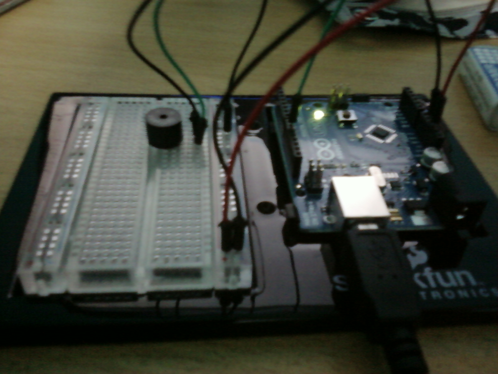
Photo: 


Tips:
  • Try to be neat with wiring and resistors
  • Remember that arrays are a group of variables of the same type (in this case Integers)
  • Change the code to make cool LED patterns

Further Work: I will change the code to be more efficient (use more loops) and make different intervals between the LED's to make different lighting patterns.

Program Modifications:
The code is the exact same as the one from the link below. 


Program: 
//LED Pin Variables
int ledPins[] = {2,3,4,5,6,7,8,9};  //An array to hold the pin each LED is connected to (ledPins[0] is   
                                                    //connected to pin 2)                                  

void setup()                            //Runs once to intialize the program
{
  for(int i = 0; i < 8; i++)        //Sets i to 0, loops as long as i is less than 8,
                                            //everytime a loop is completed i = i+1
 {              
      pinMode(ledPins[i],OUTPUT);   //Assigns all 8 ledPins with an OUTPUT Signal
  }                                  
}// ends setup method

void loop()                         // everthing inside the loop is repeated as long as there is power
{
  oneAfterAnotherLoop();            //calls the oneAfterAnotherLoop Method
}// ends the loop

void oneAfterAnotherLoop()
{
  int delayTime = 100;               //time in milliseconds   
  //Turn Each LED on with a delay
  for(int i = 0; i <= 7; i++)         //integer i is a counter, i is added once everytime a loop is run up to 8 times
  {
    digitalWrite(ledPins[i], HIGH);   //Turns on LED #i everytime this runs 
    delay(delayTime);                 
   }                                          // ends the for loop                                                                        
  //Turn Each LED off with a delay
  for(int i = 7; i >= 0; i--)        //integer i is a counter, i is subtracted once everytime a loop is run up to 8 times
  {  
    digitalWrite(ledPins[i], LOW);   //Turns off LED #i each time this runs
    delay(delayTime);                
  }                                                                                                                                                 
}// ends oneAfterAnotherLoop method

Saturday, October 8, 2011

Circuit-01 Blinking LED

Purpose: To make one LED light blink on and off

Equipment: 

  • Arduino x 1
  • Breadboard x 1
  • Arduino Holder x 1
  • CIRC - 01 Breadboard Sheet x 1
  • 5mm Yellow LED x 1
  • Wire x 3
  • 330 Ohm Resistor x 1


References:


Program Details:
This experiment is the first one so it introduces all the basic concepts of arduino and circuits to a user. One concept it shows the user is that you a resistor should be placed in your circuit to avoid blowing up the LED or the arduino board. A second concept it shows is the concept of ground and positive electricity. A wire should be connected from digital ground into the negative column in the breadboard. This will ground all electricity coming into the whole column. The same applies to positive electricity, the entire column will become positive. A third concept explained is the LED position. The larger lead/pin must go into the positive energy flow and the shorted lead/pin must go into the ground. Finally, the last concept is that a wire may also be connected from any of the positive or negative column pins into one of the 30 horizontal rows and that will make the whole row positive or negative.

As well as hardware concepts, software concepts are introduced to the user as well. The first method, the void setup method, is used to initialize the program. The second method, pinMode, is used to set  a pin (determined by an integer) as an output. The third method, digitalwrite, uses the integer and makes the LED on that pin either turn on(HIGH) or turn off (LOW). The final method, delay, uses a number (in milliseconds) to delay time before running the next line of code. The last three methods are in loop meaning that they will run repeatedly as long as there is power connected to the arduino.  

To create Circuit-01, we simply followed the breadboard sheet. We first connected a wire from 5v to a pin on the positive column. Then we connected a wire from Digital Ground to a pin on the negative column. A 330 ohm resistor was placed from a negative pin into row 11. The only difference in our circuit was that we connected a wire from Pin11 instead of Pin13 into row 10.

Time to complete: 5 mins to set up Arduino Board
                               5 mins to write the program

Results: When the code was first inputted into the arduino, nothing happened.Soon after, it was discovered that we had not connected the wire to pin13 but rather to pin5 because we had skipped that step. So the program was fixed but the LED still didn't run. Then we discovered that the the LED was placed backwards, as in the longer lead was placed into the negative flow. After we switched that, the LED blinked and the exercise was completed.

Photo:

Tips:
  • Place LED leads correctly 
  • Make sure you have a resistor in your circuit
  • Make sure your programmed pins and your physical arduino pins are the same
  • Remember that Ground is negative and all PIN numbers are positive (this includes Analog Pins)
Further Work: I will change the delay times in the program as well as add more code to the loop to see the capabilities of the LED. 


Program Modifications:
The program is almost the same as the program in the link below.
The only modifications were the change from PIN13 to PIN11.


Program:
int pin11 = 11;                                            // Holds the Pin number that the LED is connected to

void setup()
{
  pinMode (pin11, OUTPUT);                        //Assigns the pin with an output
}// ends the void setup method

void loop()
{
  digitalWrite(pin11, HIGH);                        // Turns on the LED at pin11 
  delay (1000);                                          // Creates a delay for 1000 milliseconds / 1 second
  digitalWrite(pin11, LOW);                        //Turns off the LED at pin11
  delay(2000);                                          //Creates a delay for 2000 milliseconds / 2 seconds
}// this ends the loop